Background
As children my sister and I had an NES with one of those 350-in-1 cartridges and played a fair amount of random Nintendo games as children. She recently commented that it would be fun to play those games again.
I remembered seeing RetroPie being used as an emulation distribution and told her it would be possible to build a small computer to emulate classic games. I then said - in a very legally absolving and morally forthright way - that using such a computer to emulate games that had been obtained by any method other than purchasing it would be illegal and told her under no circumstances would that be permissible if I built it for her.
I then - purely for educational purposes - set to work.
Research
I imagined building something similar to a Nintendo NES Classic Mini using a Raspberry Pi but quickly came upon different forms and cases that intrigued me. I decided on a design from a website called HowChoo that involved placing the Pi into the controller itself and making that the hub for the system. I liked the idea of shrinking the system down to the controller and decided to go with this. After reading the HowChoo tutorial on how to do this with a NES controller, it occurred to me it could be done with a SNES controller giving more buttons (and the opportunity to emulate more games).
HowChoo had a tutorial for how to do this with a SNES controller, but it seems to have been taken down. Internet Archive to the rescue. The SNES tutorial I followed can be found here. A YouTube video giving an overview can be found here
Material
- SNES Controller
- Raspberry Pi Zero 2W
- Raspberry Pi heat sink
- Mini HDMI to HDMI cable (10 ft)
- Micro USB to USB cable (10 ft)
- USB power adaptor
- M2.5 x 5mm screws
- Soldering equipment
Obtaining the SNES controller for a decent price was surprisingly difficult. They’re cheapest in rural areas and eaten up by retro games enthusiasts in cities. I managed to find one and made my first ever trip into a pawn shop! The tutorial calls for a Raspberry Pi Zero W but it was the same price for the Pi Zero 2W. The cables needed to be long enough to sit away from the TV and are pretty easy to find. I had to go down a rabbit hole learning what a “M2.5 x 5mm screw” is. I learned why there are tens of thousands of screws and fasteners. After a lot of digging and reading online I asked a friend who has been building custom keyboards and he read me into the world of screw sizes and nomenclature. I ended up buying the 5 screws from here. I had considered just using a glue gun to secure the pi in the controller, but you cannot remove the microSD card from the Pi while it is secured in the controller base.
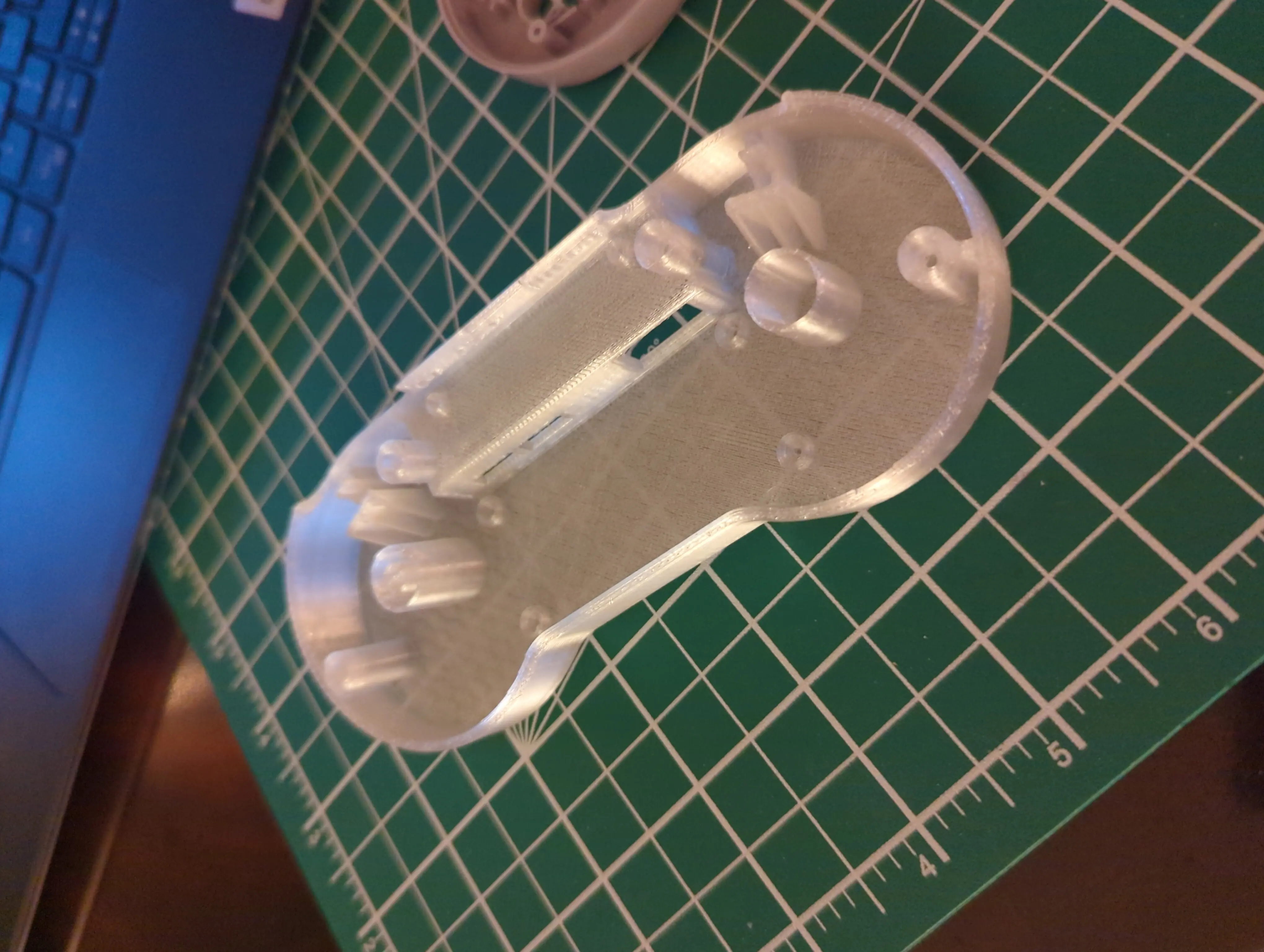
To fit the Pi into the controller requires a new rear piece for the controller, which is easily created with a 3D printer and the free blueprint found here. There are plenty of places to print this and ship it to you…unless there’s a national postal strike in Canada and this delays the project for over a month! Once the strike was over, I had it printed in transparent PETG (material).
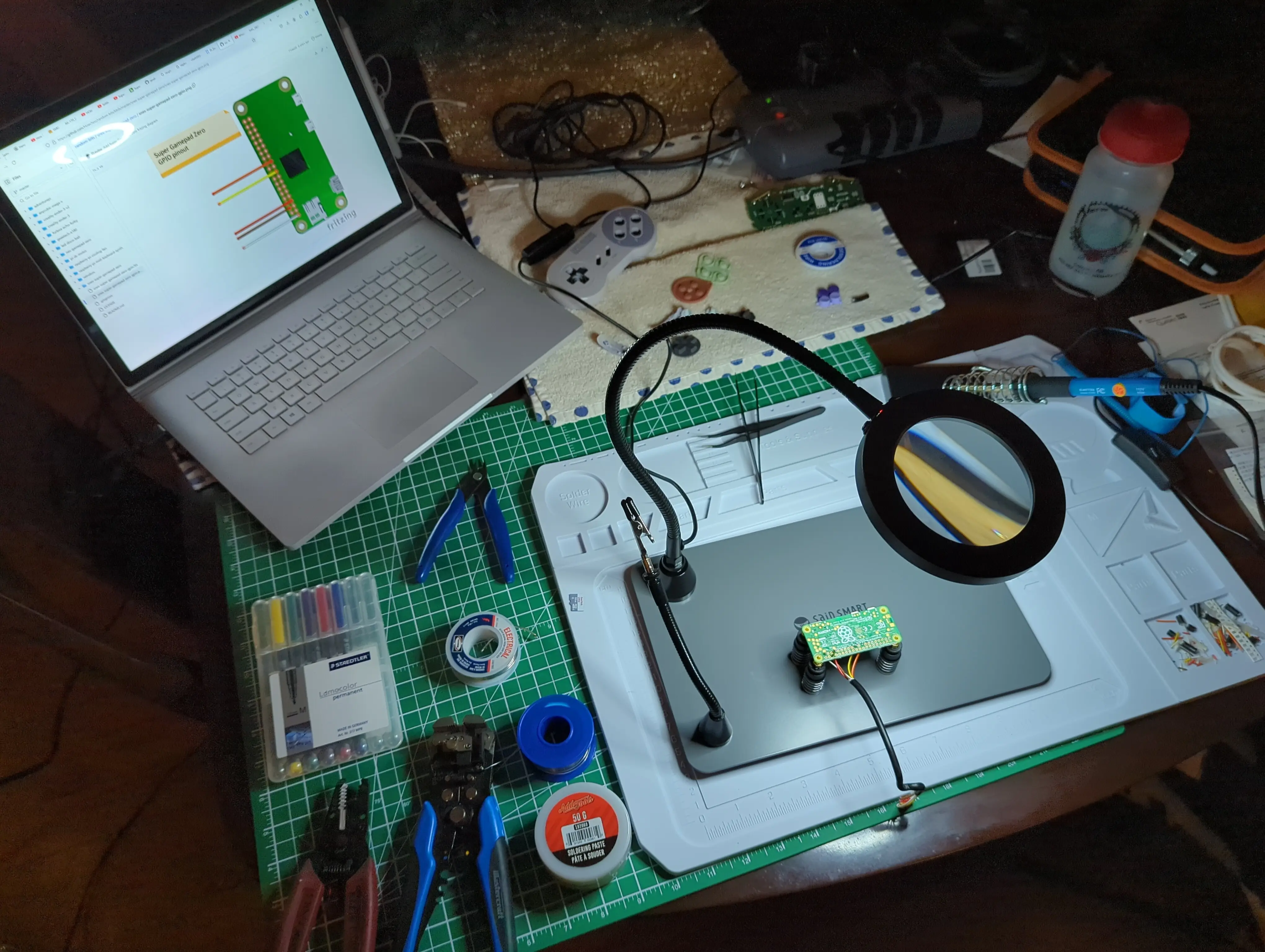
Finally, I’ve never done any soldering but took this opportunity to start. I did a lot of research on soldering and soldering irons to buy. At the urging of friends I opted for the cheapest soldering iron because I had so little soldering to do, and I could upgrade later. I DID opt to spend some treasure on some soldering tools (helping hands) to make the soldering easier.
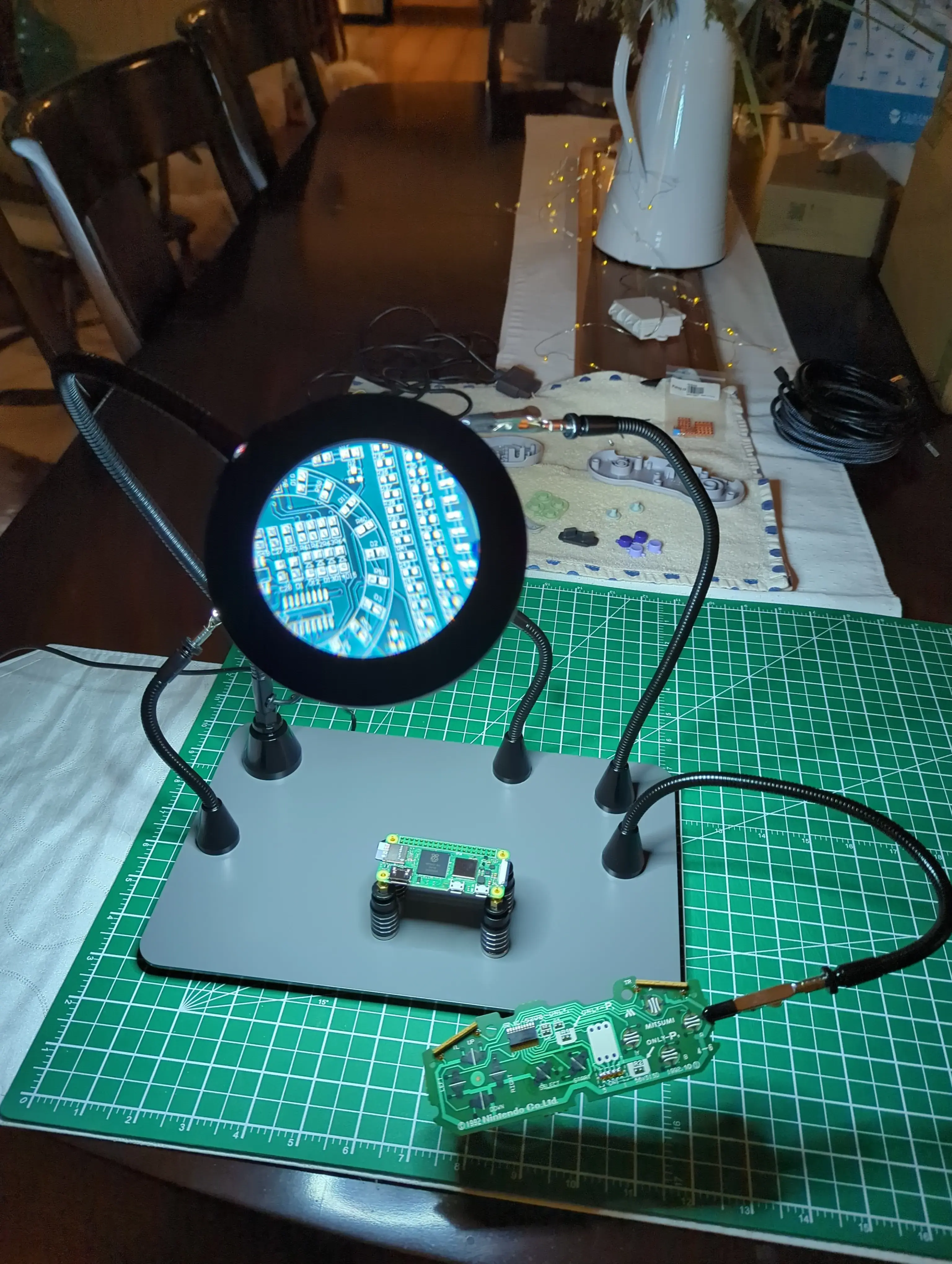 When I sent this photo to my friends they accused me of “cosplaying” as someone who solders. It didn’t sting and I don’t think about it a lot.
Assembly
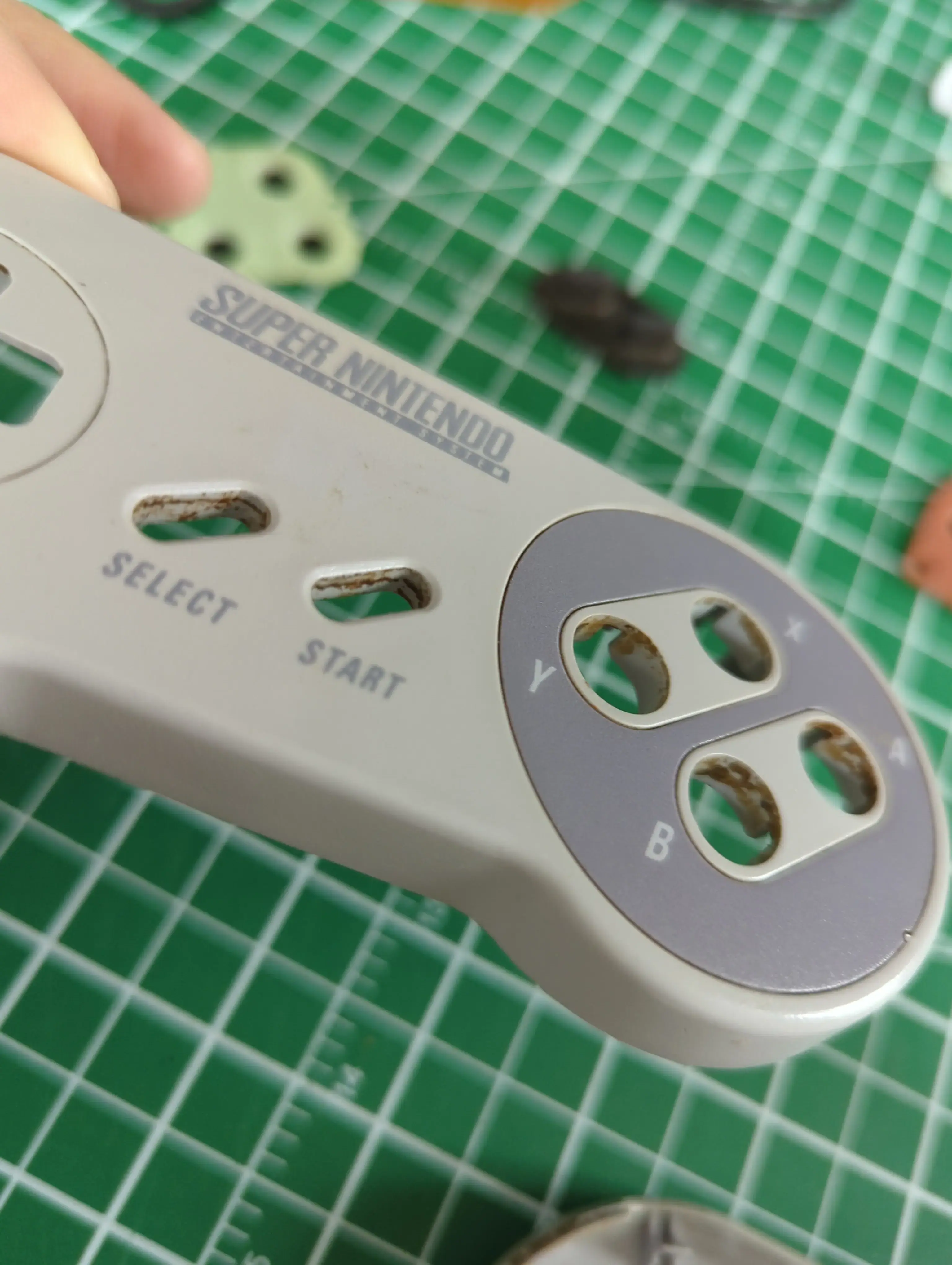
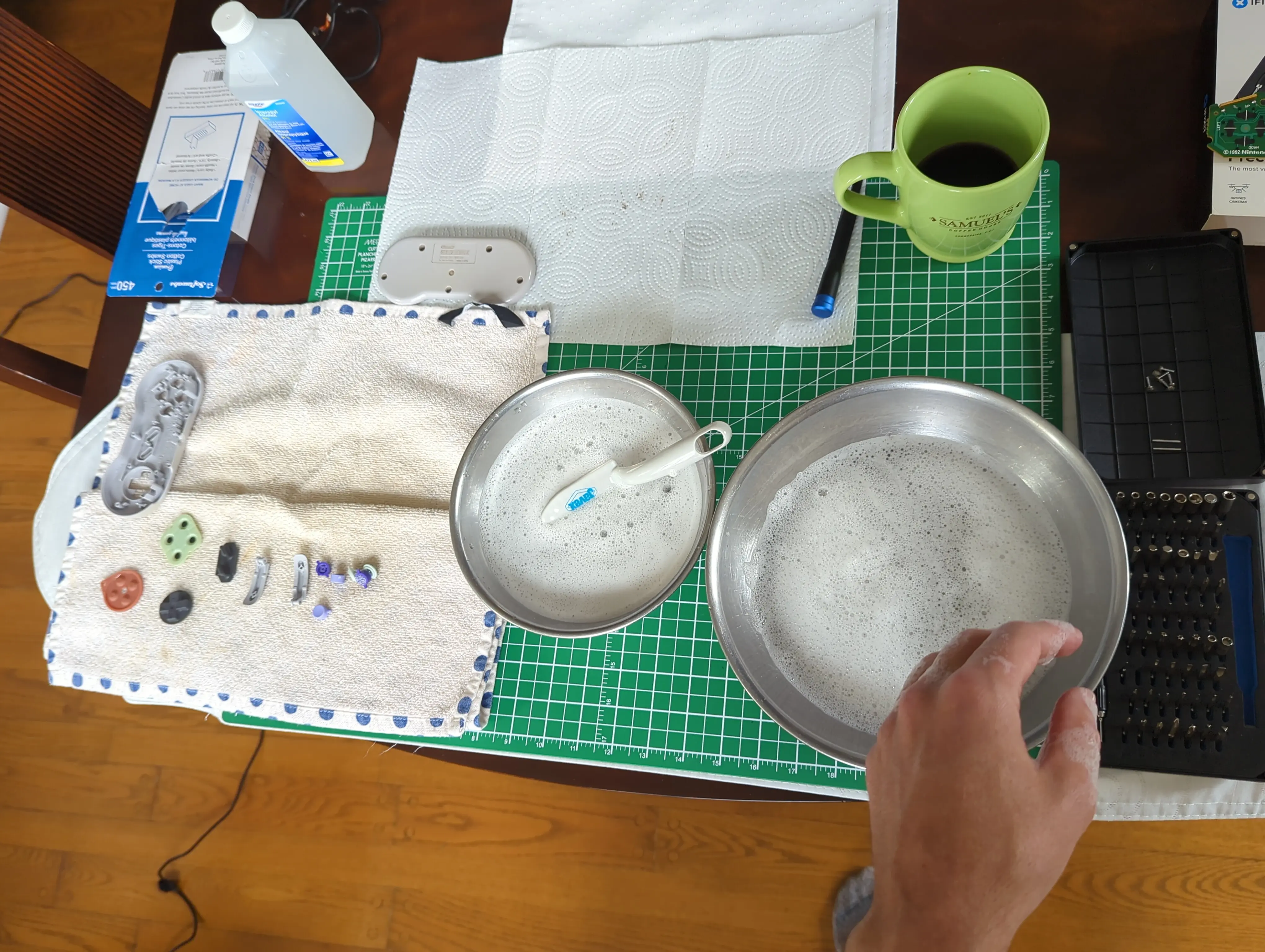
Step one was to disassemble the controller. The immediate next step was to deep clean the controller. 30+ years of being handled makes such things incredibly dirty.
I then tried soldering on a practice board I bought to make sure I knew what I was about to do.
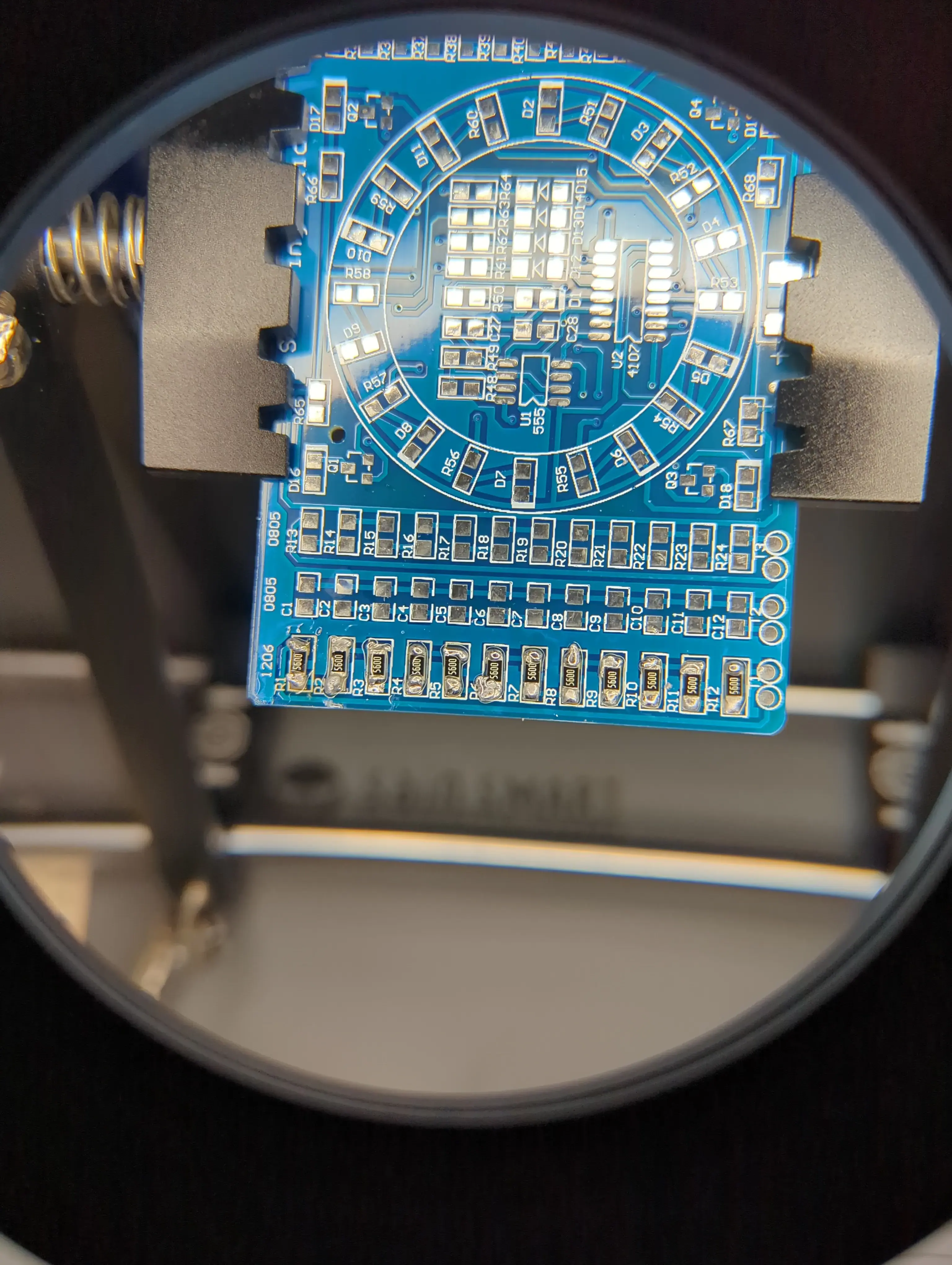 It’s a poor craftsman who blames their tools, so I won’t blame the $11 soldering iron I bought for how difficult I found soldering. Eventually I got the hang of it and was ready to wire the controller to the GPIO pins of the Pi.
 I used the diagram provided to know where to solder the wires. I wanted to know what these particular pins were doing and found this excellent resource for explaining Raspberry Pi GPIO pins.
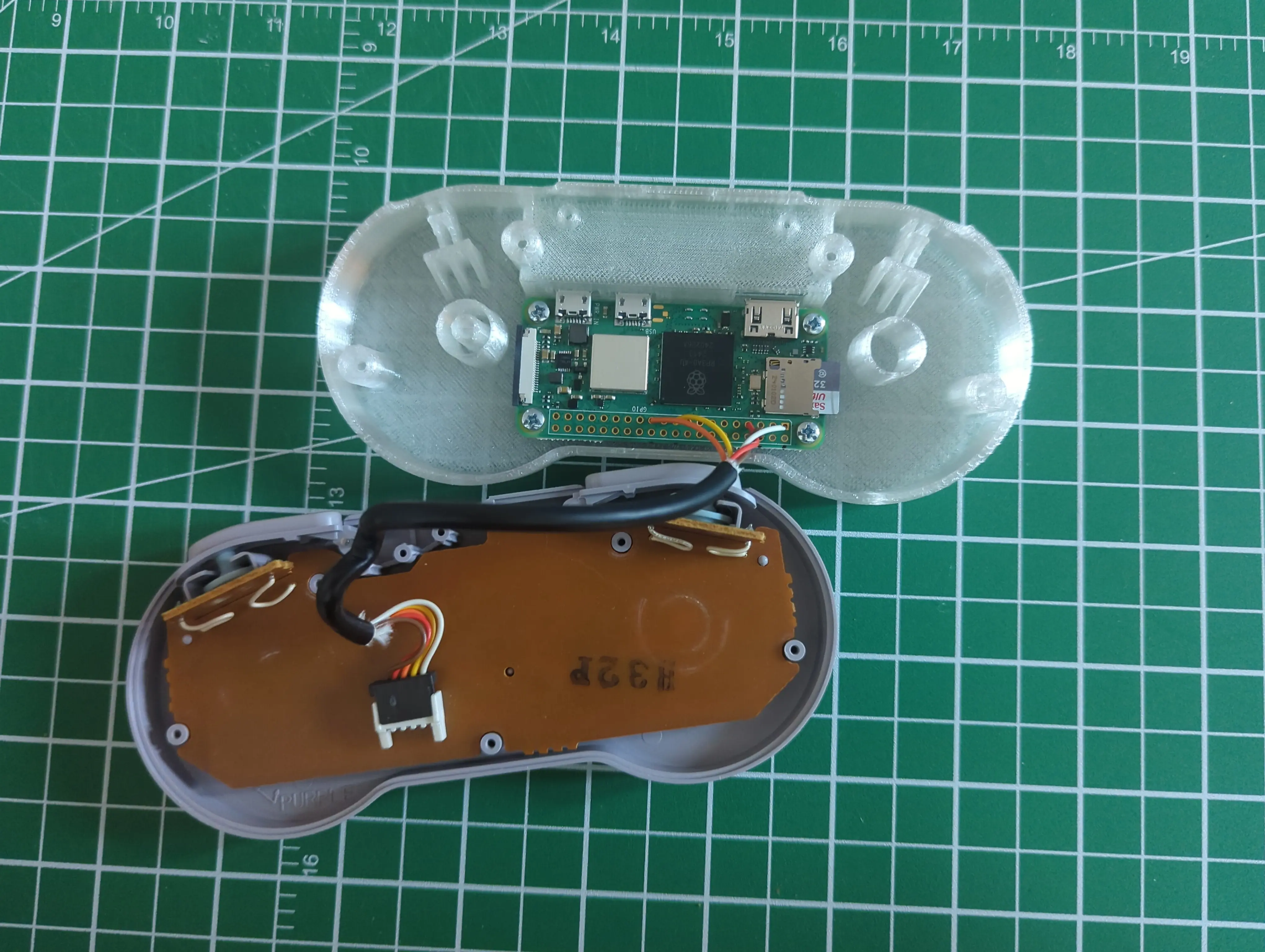
Once finished, it looked like this:
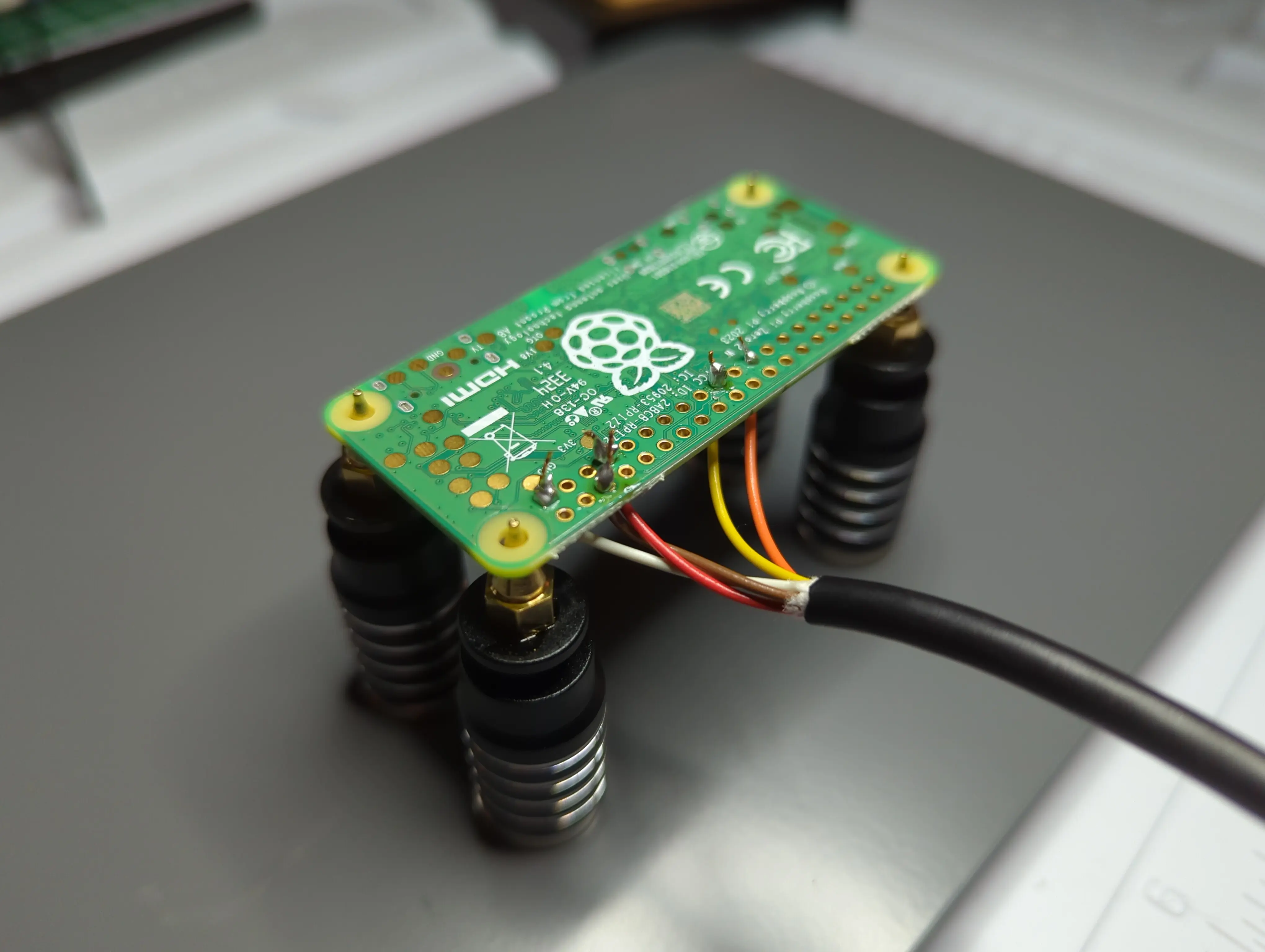 If you plan to try this, note that these cables are quite small and easy to damage and break when stripping the plastic off of them.
I then reassembled the controller.
 The M2.5 x 5mm screws didn’t get any purchase in the plastic initially. I used the soldering iron to open the screw holes a bit and once they had some bit they screwed in with a bit of effort.
 With all the parts and original board back in the controller.
I then connected to a TV and ran the setup steps described in the tutorial but it didn’t detect the controller. I spent a bit of time trying different configurations and restarting, but nothing worked. I did read the gpio configuration section of the RetroPi manual and it is fantastic!
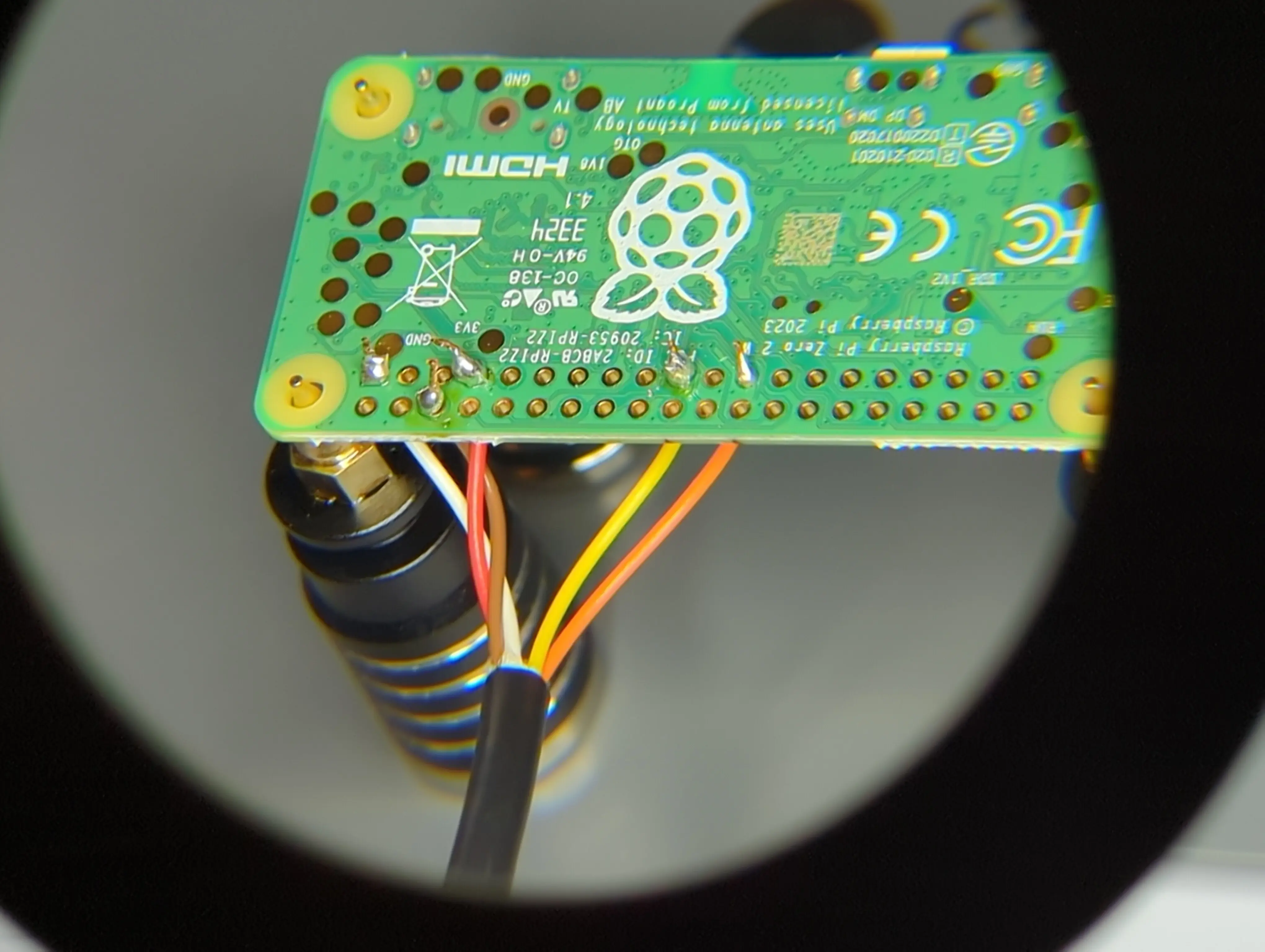
I guessed the problem might be the soldering, so I clipped off the extra solder seen here:
 I’m not sure if this actually changed anything, but on the next boot the controller was detected. I downloaded a ROM (one for a NES game I own) and tested it. Worked like a charm!
Finished Product
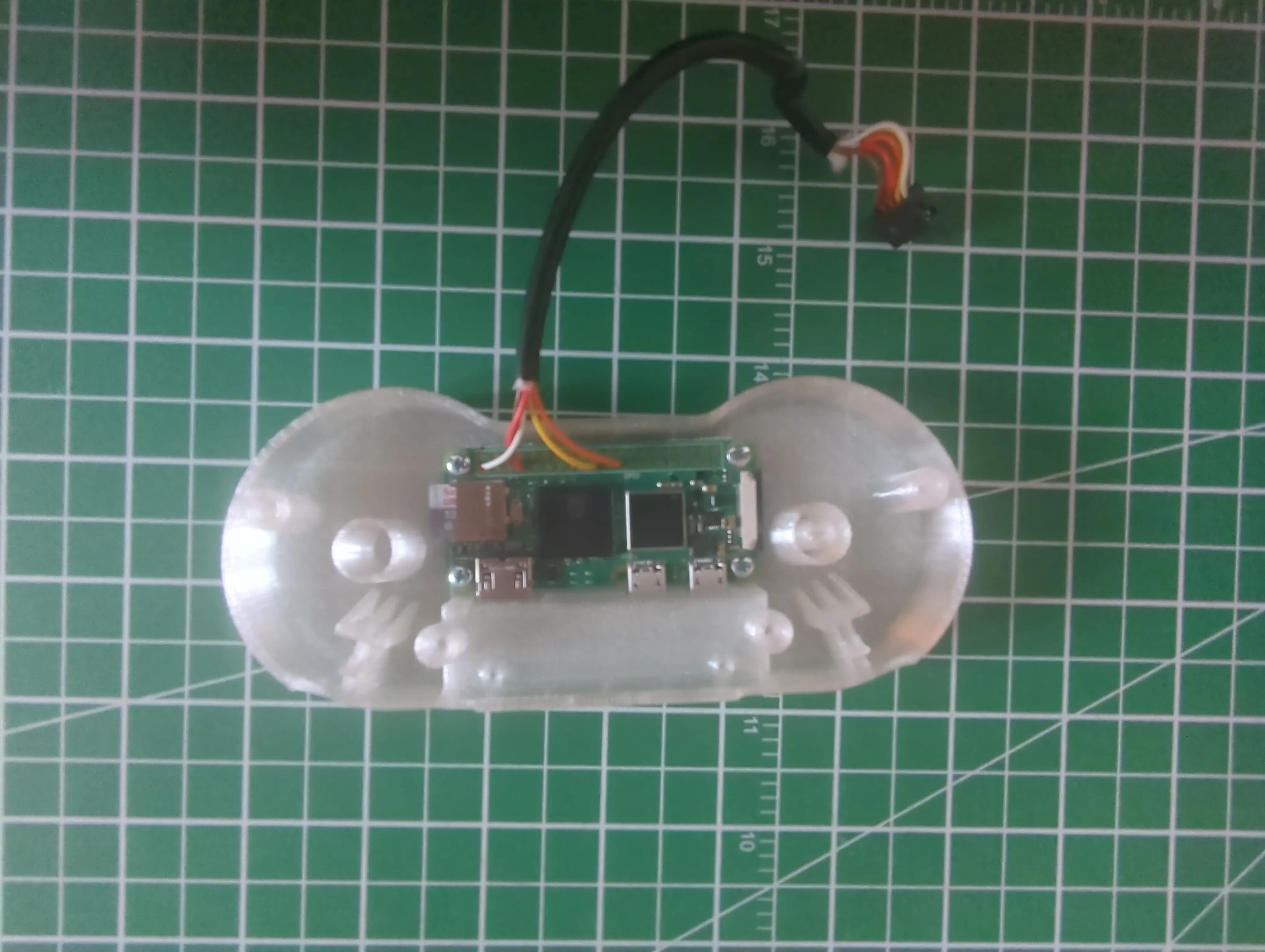
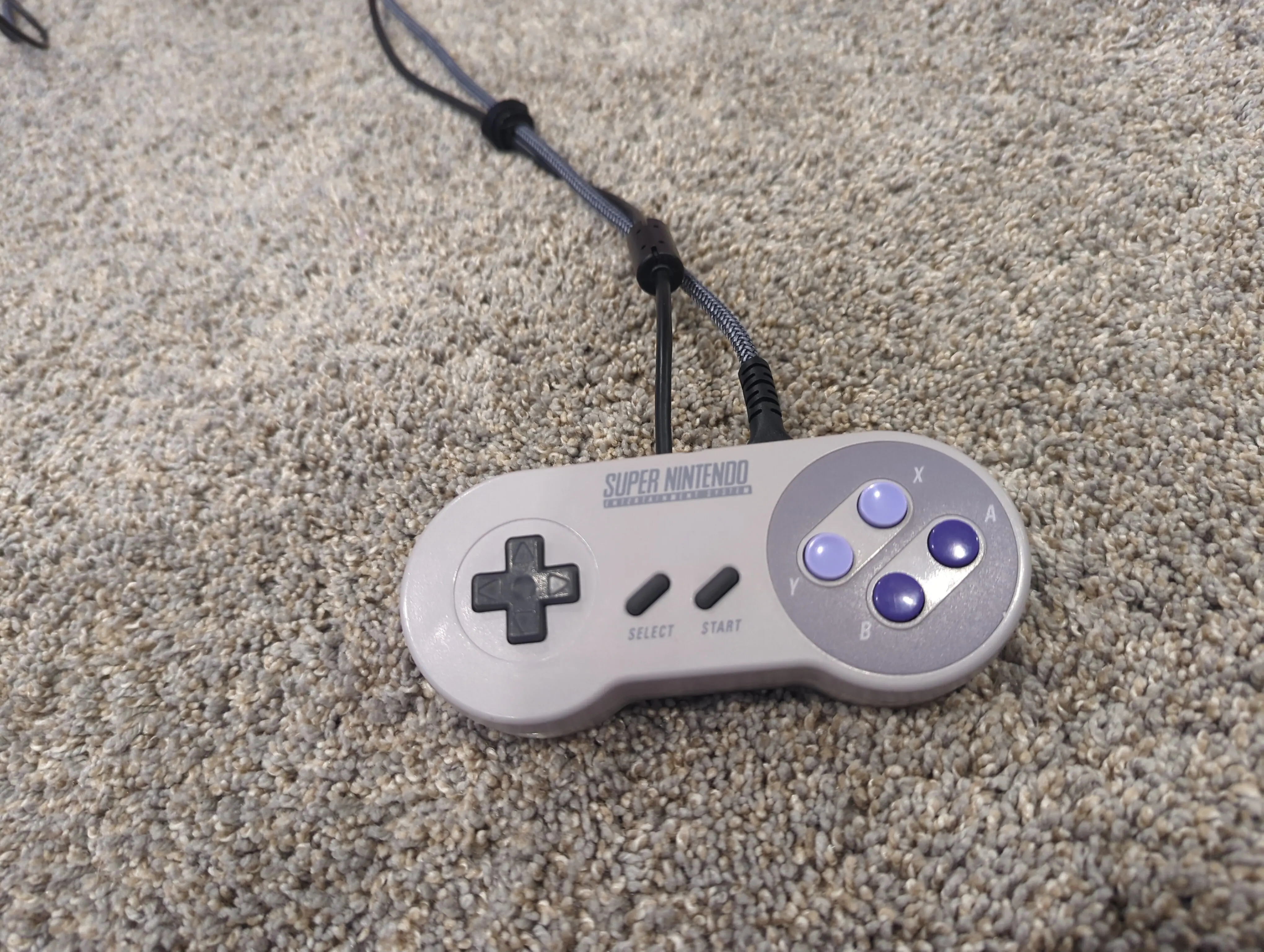
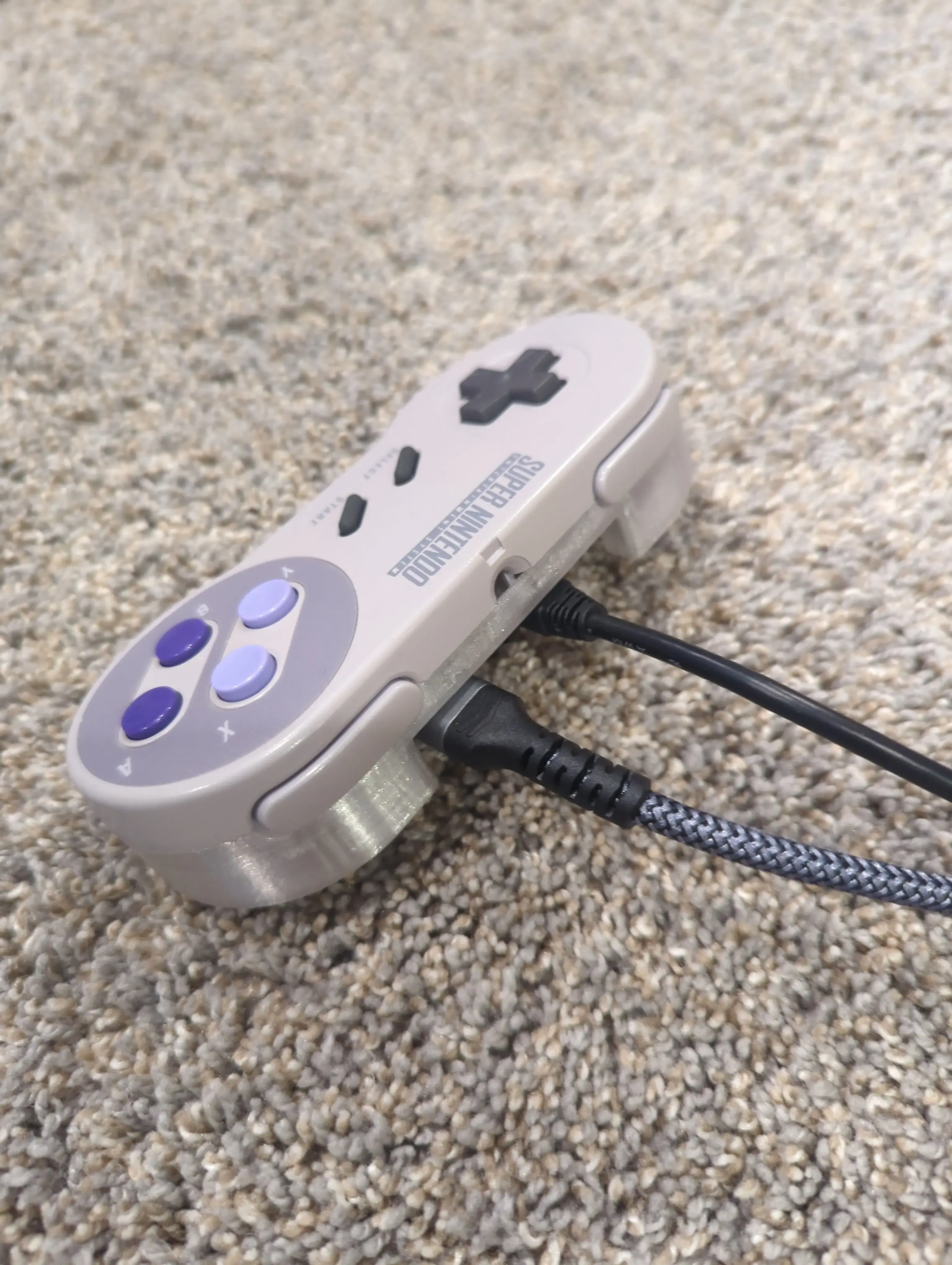
This is what it looks like with wires connected:
Next Steps
I’d like to add a LED to show when the Pi is powered. This shouldn’t take long, I’m just waiting for the parts!